Working principle and process flow of automatic CNC pipe bending machine
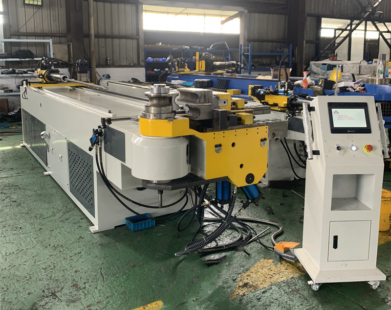
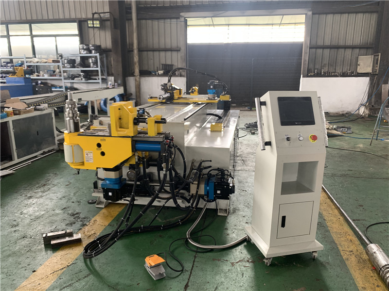
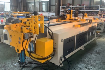
CNC pipe bending machine is a new type of pipe bending tool with pipe bending function and top function. It has many advantages such as reasonable structure, safe use, convenient operation, reasonable price, fast loading and unloading, and one machine for multiple purposes.
?Structure and working principle
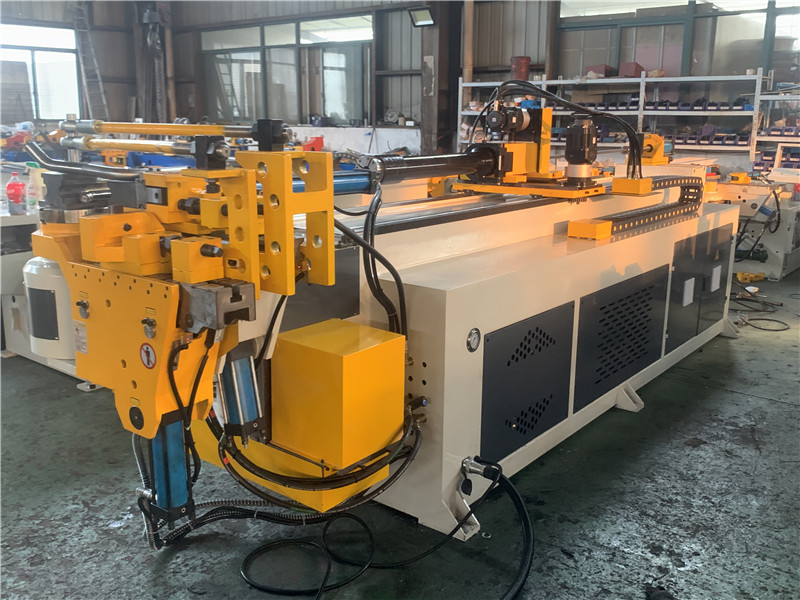
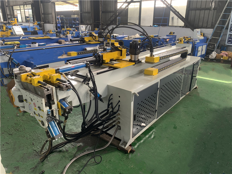
???It is composed of electric oil pump, high pressure oil pipe, quick joint, working oil cylinder, plunger and elbow parts. The high-pressure oil output by the electric oil pump is sent into the working oil cylinder through the high-pressure oil pipe, and the high-pressure oil pushes the plunger in the working oil cylinder to generate thrust, and the pipe is bent through the pipe bending parts. The CNC pipe bending machine is suitable for factories, warehouses, docks, Construction, railways, automobiles, etc. are installed and repaired. In addition to the pipe bending function, it can also be used as a separate hydraulic jacking machine by removing the pipe bending part (oil cylinder).
Working principle of automatic CNC pipe bending machine
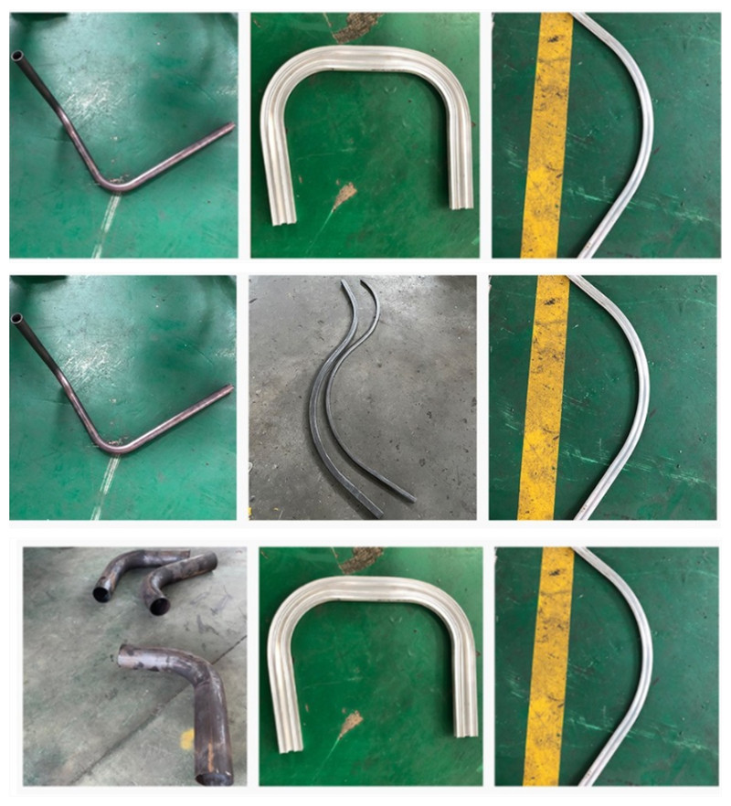
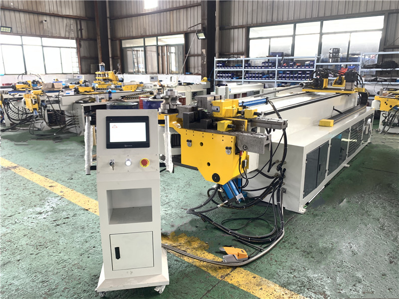
It is mainly composed of three parts: mechanical part, hydraulic system and PLC control system. The mechanical part is mainly composed of turning pipe clamping device: bending pipe transmission device: booster device: bed and pipe bending die. The working principle of pipe bending is shown in the figure: the pipe bending die is fixed on the main shaft and rotates with the main shaft, and the pipe is fixed on the clamping groove of the fan-shaped pipe bending die through the clamping die. The mobile booster guide pressing chute is close to the outer side of the tube blank. When the bending die rotates by an angle, the tube is wrapped around the circumference of the bending die, and the rotation angle of the bending die is the bending angle. The three-dimensional multi-bending of the same radius realized on the same pipe fitting mainly includes three actions: straight-line feeding space turning pipe and pipe bending. In the next bend, a space bend with the same bend radius can be obtained. The bending radius determines the bending radius. With the rapid development of my country’s power industry, the continuous improvement of the design and manufacturing level of power station boilers, and the continuous emergence of new furnace types, the demand for the number and specifications of various bent and formed pipe fittings in the boiler manufacturing industry In the continuous increase, the pattern is constantly renovated, and at the same time, higher requirements are placed on the bending accuracy and surface quality. However, when the old pipe bending machine is processed, it can only complete one bending at a time, often loading and unloading, the production efficiency is low, and the synchronous improvement of output and quality cannot be achieved. The application of PLC in the hydraulic pipe bending machine control system overcomes The relay contact control system is susceptible to environmental interference, high failure rate and difficult maintenance. In addition, it can adapt to the changes of new process requirements only by modifying the software:
Process flow of automatic pipe bending machine
When in use, the coil is energized by the wire, and after the electricity is energized, the pressure plate is attracted, so as to realize the clamping of the thin plate between the pressure plate and the base, so as to meet the needs of various workpieces. Components only cooperate with each other. In order to make it work better, let’s talk about the working principle of each part of the pipe bending machine
1) Synchronization system: The machine consists of a mechanical synchronization mechanism composed of torsion shaft, swing arm, joint bearing, etc., with simple structure, stable and reliable performance, and high synchronization accuracy. The mechanical stop is adjusted by the motor, and the numerical control system controls the value.
2) Slider part: hydraulic transmission is adopted, and the slider part is composed of a slider, an oil cylinder and a mechanical stopper fine-tuning structure. The left and right oil cylinders of the pipe bending machine are fixed on the frame, and the piston (rod) drives the slider to move up and down through hydraulic pressure, and the mechanical stop is controlled by the numerical control system to adjust the value.
3) Stopper mechanism: The stopper of the pipe bender is driven by a motor, and the two screw rods are moved synchronously by chain operation, and the size of the stopper is controlled by the numerical control system.
4¥ worktable part: operated by the button box, the motor of the pipe bending machine drives the material stopper to move back and forth, and the moving distance is controlled by the numerical control system, and the minimum reading is 0.01 mm
The mutual coordination of various parts of the CNC pipe bending machine comprehensively improves the efficiency, accuracy, maintainability, versatility and safety of the system, reduces manufacturing materials, and is very convenient to use.
