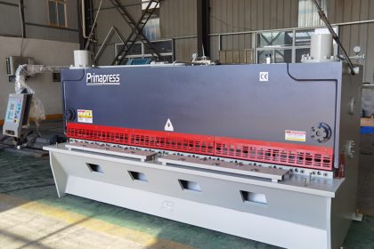
The main components and functions of the hydraulic CNC shearing machine
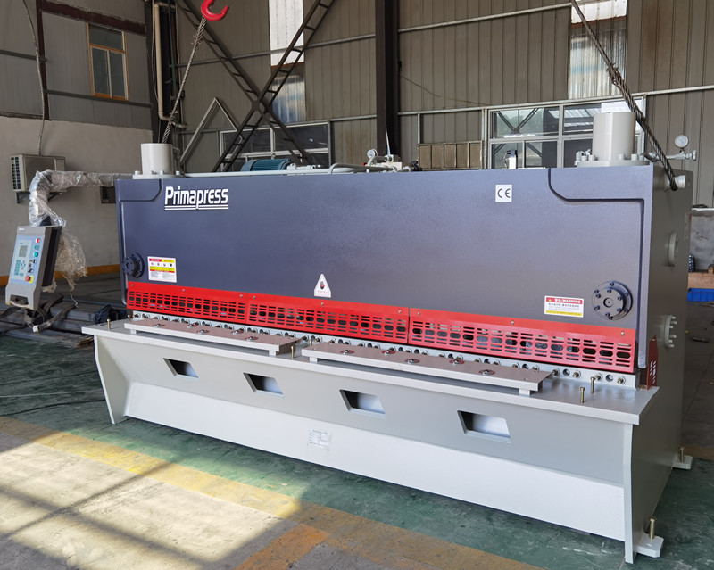
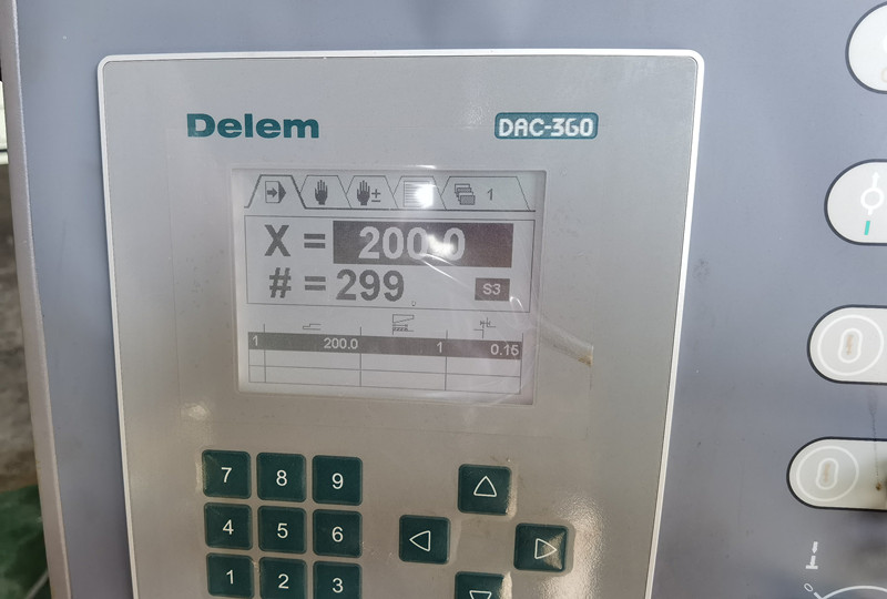
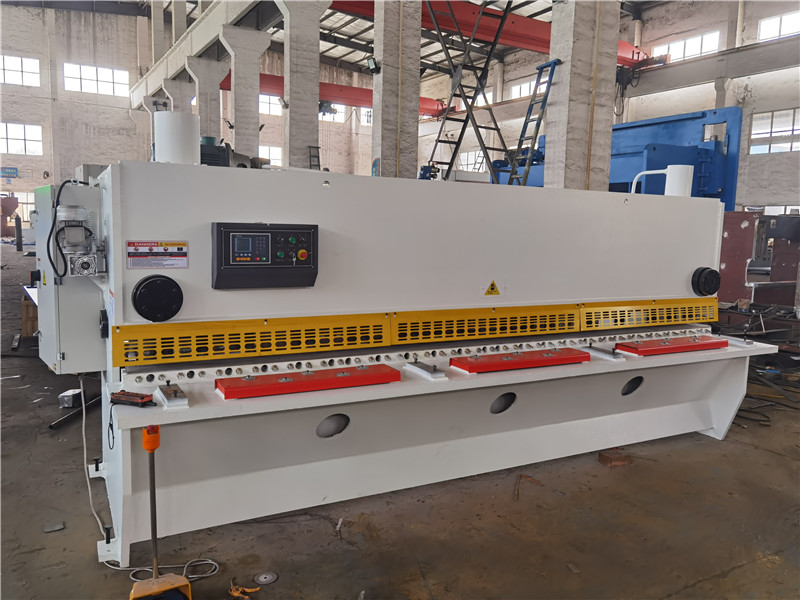
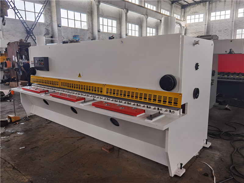
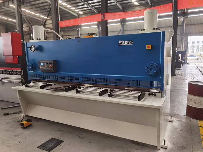
The working process of the CNC shearing machine is: after pressing the run key, assuming that the actual position and the target position differ by more than 2mm, the deceleration distance can be set by parameters), the terminal outputs the potential signal; if the difference between the actual position and the target position is less than the deceleration distance, the terminal Output pulse signal (slow speed signal), the running indicator on the panel flashes fast and slow respectively, indicating fast or slow running status, when the actual position and the set position are equal, the running indicator will light for a long time, indicating that it stops in place. However, there is also a parameter decision for stopping, which can set the time that the actual position and the set position coincide (dwell), so that the set position can be positioned more accurately. For example: if the slow speed is faster, the overlapping time of the two is also shorter, and overshoot may occur at this time. If a longer dwell time is set, the positioning will not end at this time, and the positioning will continue to be repeated at the slow speed to a higher speed. Accurate position, but the dwell time for judgment should not be too long, otherwise the positioning speed will be affected. The main components of the hydraulic shearing machine are: frame assembly, upper tool rest device, lower tool rest device, pressing device, shearing edge side clearance adjustment, pressing device, etc. Due to the introduction of the hydraulic system, the electrical performance of the equipment has been improved and the automation level of the equipment has been improved. It has the characteristics of simple operation, high reliability and convenient modification of process parameters.
(1) Rack assembly: The whole rack consists of left and right racks (welding parts), beams and guide table. The upper part supports the upper tool rest driving device, the steel plate pressing device, the synchronizing device, the upper tool rest and so on. The left and right frames are bolted together with the beam and the lower tool frame to form a rigid frame that can withstand shearing force.
(2) Upper tool holder device: It is mainly used to fix the upper blade and move up and down along the slideway in the frame under the drive of the hydraulic cylinder to complete the shearing action. The upper shearing blade is closed on the upper knife box through the bolt handle, and the upper knife box is fixed on the upper knife frame through the locking cylinder, which is clamped by the spring and released hydraulically. A hinged double-parallelogram mechanical synchronizing mechanism is arranged between the upper tool rest and the upper beam of the frame. The two shearing cylinders are respectively installed on both sides of the shearing machine frame. The two sides are connected with spherical surfaces, and the two shearing cylinders simultaneously drive the upper tool holder equipped with the upper shearing blade to move up and down in the frame equipped with bronze and steel lining plates to complete the shearing.
(3) Lower tool holder device: It is mainly used to fix the lower blade, integrates with the left and right frame handles, bears and transmits shearing force, and completes the process of shearing steel plates together with the upper tool holder. The upper surface of the lower blade is 10mm lower than the roller table. Water is passed through the lower tool holder for cooling. The lower cutting edge is closed on the lower knife box through the bolt handle, and the lower knife box is fixed on the lower knife frame through the locking cylinder, which is clamped by the spring and released hydraulically.
(4) Adjustment of the side clearance of the shearing edge: It is adjusted by two wedge systems, one of which is installed upstream of the shearing edge and the other is installed downstream of the shearing edge. The two wedge systems are respectively controlled by two hydraulic motors. Drive four jacks (worm worm gear sleeve nut screw) to move the wedge up and down, so that the upper tool table can move horizontally, and the side clearance of the cutting edge can be adjusted.
(5) Pressing device of hydraulic plate shearing machine: In order to prevent the steel plate from moving during shearing and to improve the quality and geometric accuracy of the shearing section, a hydraulic pressing plate device is installed in front of the frame of the cutting and shearing machine. After the sheared steel plate is transported to the position to be sheared, the hydraulic cylinder presses the pressure plate on the steel plate, and the shearing mechanism cuts the steel plate.
