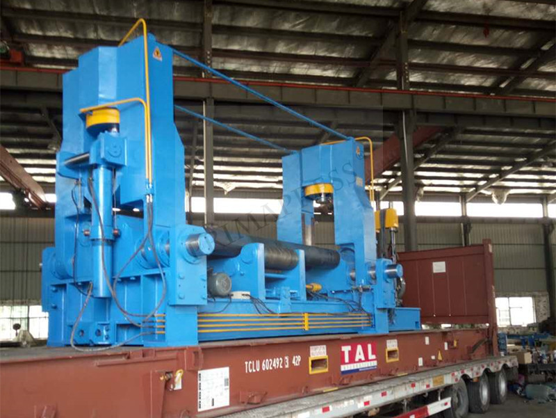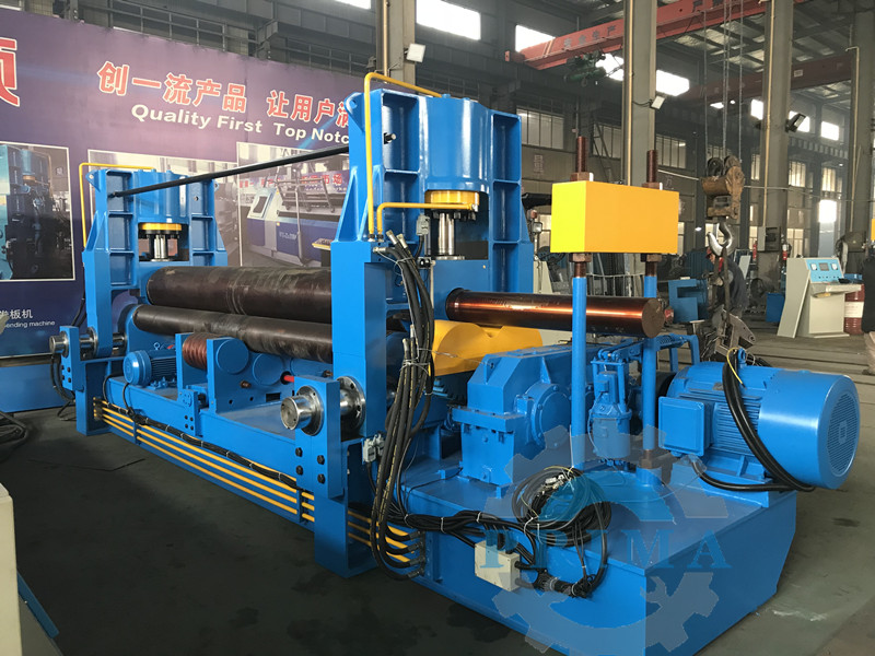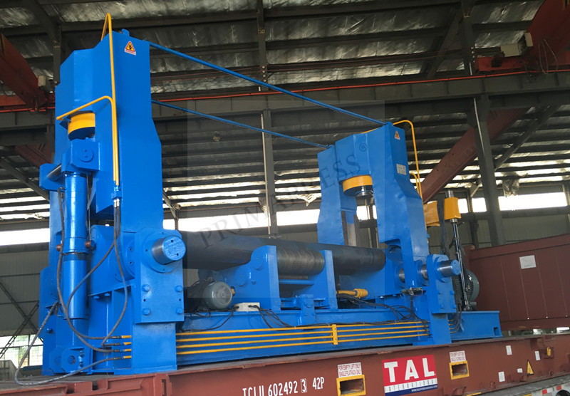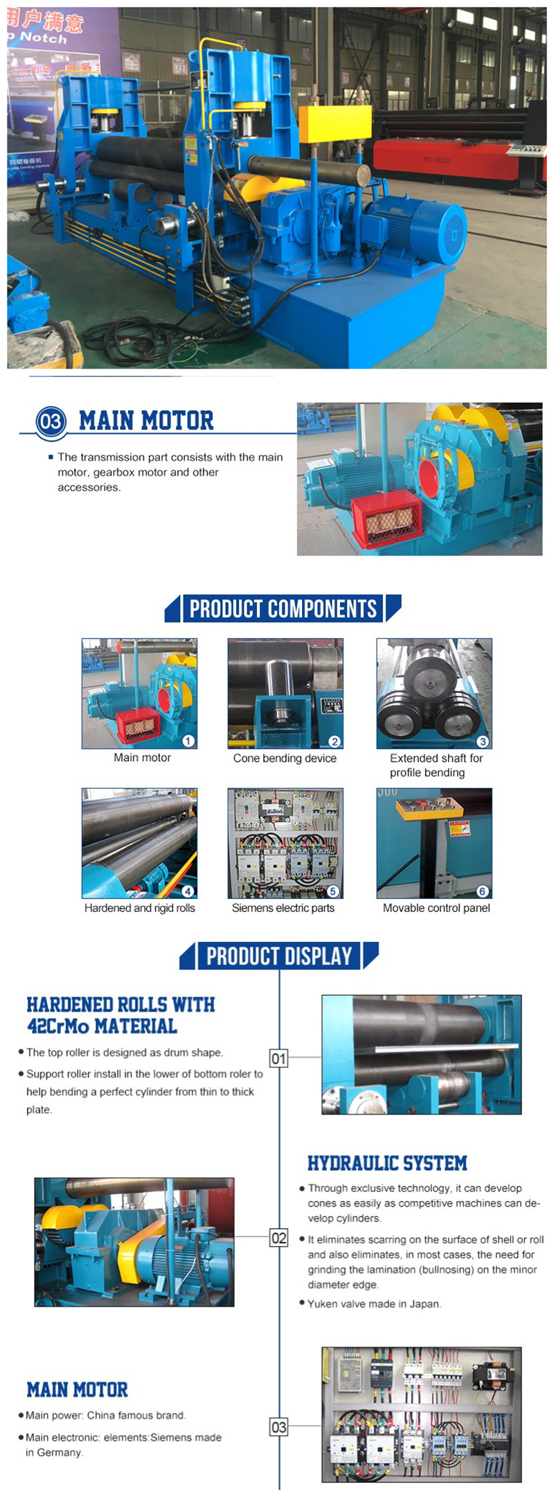
The purpose, main structure and operation process of the upper roll universal bending rolling machine
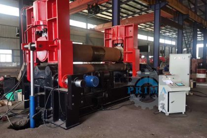
The upper-roll universal three-roller plate bending rolling machine is a general equipment for bending rolling metal sheets into cylindrical, arc or other shapes. Almost all steel materials are formed into a cylindrical shape and rolled by a plate bending rolling machine. The rolling machine equipment is widely used in boiler, shipbuilding, petroleum, woodworking, metal structure and other machinery manufacturing industries. To
The specific structure of the upper-roll universal three-roller plate bending rolling machine is explained as follows:
(1) Upper roller device
The upper roll device is mainly composed of the main cylinder, the upper roll chock, the upper roll, and double-row self-aligning bearings. The upper roll is an important part of the plate rolling machine. The journals at both ends of the upper roll adopt extra-wide double-row spherical roller series rolling bearings. Due to the use of spherical roller bearings, it is beneficial to tilt the main roll and facilitate taper winding. The two main oil cylinders provide the pressure required to roll the plate. To
(2) Horizontal moving device
The horizontal moving device is powered by the moving motor, and the horizontal movement of the upper roller device is driven by the reducer, worm gear, and screw nut mechanism to realize asymmetrical rolling of the sheet. To
(3) Lower roller device
The lower roller device is composed of a lower roller, a lower roller bearing seat, an input gear, and a sliding bearing. The lower roller is an important part of the plate rolling machine, it is suitable for normal temperature conditions and low-speed heavy-duty places. To
(4) Roller device
The supporting roller device is composed of supporting rollers, inclined wedge mechanism, and supporting roller adjusting hand wheel. There are a set of rollers, which can be adjusted up and down according to the load size of the rolled sheet specification. To
(5) Main transmission device
It consists of a main motor, an electro-hydraulic push rod brake, a cylindrical gear reducer, and an output gear. To
(6) Tipping device
The tipping device consists of a ram, a tipping cylinder, etc. Installed on one side of the overturned frame, used for the overturning and recovery of the overturned frame. The overturning of the overturning device facilitates the removal of the product along the axial direction of the roller. To
During the operation of the hydraulic three-roller bending rolling machine, the staff must coordinate with each other and obey the command of the person in charge of the bending rolling. There is no password and it is forbidden to start the machine. Hydraulic three-roller bending rolling machine specifications flat steel plates, stainless steel plates, aluminum plates and other plates, pass between the three working rolls (two lower rollers and one upper roller) of the hydraulic three-roller bending rolling machine, and press down and down by the upper rollers. The rotating movement of the roller causes the metal plate to be continuously bent through multiple passes, producing permanent plastic deformation, and rolling it into the required cylinder, cone or other special-shaped products. Points to note when operating the hydraulic three-roller bending rolling machine: operate strictly in accordance with the bending rolling process and operating methods. When the upper roller is lifted to the limit position, pay attention to the safe operation of the equipment. The hydraulic three-roller bending rolling machine can carry out the lifting of the upper roller, the tilting reset of the overturning bearing and the tilting of the upper roller only after the main drive is stopped. After the hydraulic three-roller bending rolling machine was operated last time, because the operator did not shut down the machine strictly according to the operation, the slider was stopped at the top dead center position before the machine was powered off, and the slider was not manually lowered when the machine was turned on next time. , Place the position where the upper and lower molds overlap, and perform the operation of returning to the reference point, causing the operation to fail to find the reference point. If this is the reason, you need to switch the system to manual motion, and move the slider down to the top and bottom in manual mode. When the mold coincides with the position, and then enter the semi-automatic or automatic mode, find the reference point again.
